Elastic Hand Method
The explanation of Elastic Design is lengthy, but the basis for the Icon Design Program is rooted in the calculations explained below. Upon understanding this methodology, all the other calculations will begin to fall into place. This method incorporates the shear flow check previously used and allows the flexibility of various combinations of connectors, connector strength and stiffness, and wythe thicknesses into one predictable model. This model predicts the Moment required to crack the section. Mcr is a limit state of the elastic behavior.
The following information, equations, drawings and diagrams are a summary from:
A GENERAL METHODOLOGY FOR EVALUATING COMPOSITE
ACTION IN INSULATED WALL PANELS
A report to the Precast/Prestressed Concrete Institute
as part of a Daniel P. Jenny Research Fellowship
BY
Jaiden Olsen, Salam Al-Rubaye, Taylor Sorensen, Marc Maguire
UTAH STATE UNIVERSITY
Logan, Utah
2017
Assumptions
The calculation of M cr and the midpoint deflection of the beam at M cr use the Elastic Hand Method Procedure.
The method incorporates panel geometry and Icon connector forces. The following assumptions are made:
Euler-Bernoulli beam theory applies to the individual wythes (i.e. plane sections remain plane and normal to the deflected axis)
Linear elastic material behavior (Including the Icon connectors)
The principal of superposition is valid
The slip in the Icons varies linearly along the length of the panel.
Overview
Using the above assumptions, the designer must perform an iterative procedure due to the nature of determining slip for the chosen Icon connector pattern.
Once the connector force is determined based on the end slip, a sectional analysis is performed for the controlling wythe (the cracking wythe) and deflections can be easily determined using elastic beam equations. The guessed slip will need to be checked using slip kinematic relationships, but this is accomplished using familiar mechanics equations and equivalent loads.
The cracking moment and deflection predictions of the Elastic Hand Method depend mainly on the section geometry, modulus of rupture of the concrete, the elastic modulus, and the connector forces. For the purposes of discussion, wythe outside is considered the wythe that would be in compression during wind pressure bending of a fully-composite sandwich panel and wythe inside is considered the wythe that would be in tension during wind pressure bending of a fully-composite sandwich panel.
When the program calculates wind suction the wythes are reversed so that the outside wythe is always compression and the inside is always tension. The output is then switched back to reflect the correct stresses on the wythes. In doing this the forces and deflections do not have confusing positive/negative signs.
Procedure for the Elastic Hand Method
Step 1. Assume an end slip of end connector.
The end connector is the connector at the top and bottom of the panel near the support points.
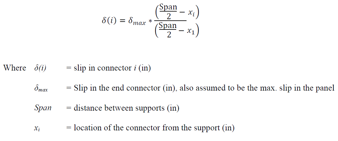
The slip in the other connectors can be calculated using:
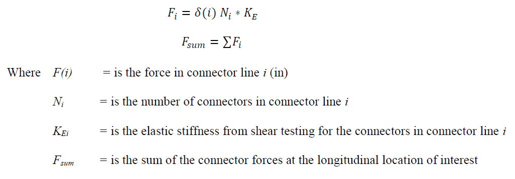
Step 2. Calculate the forces in each line of connectors.
Step 3. Calculate the cracking moment.
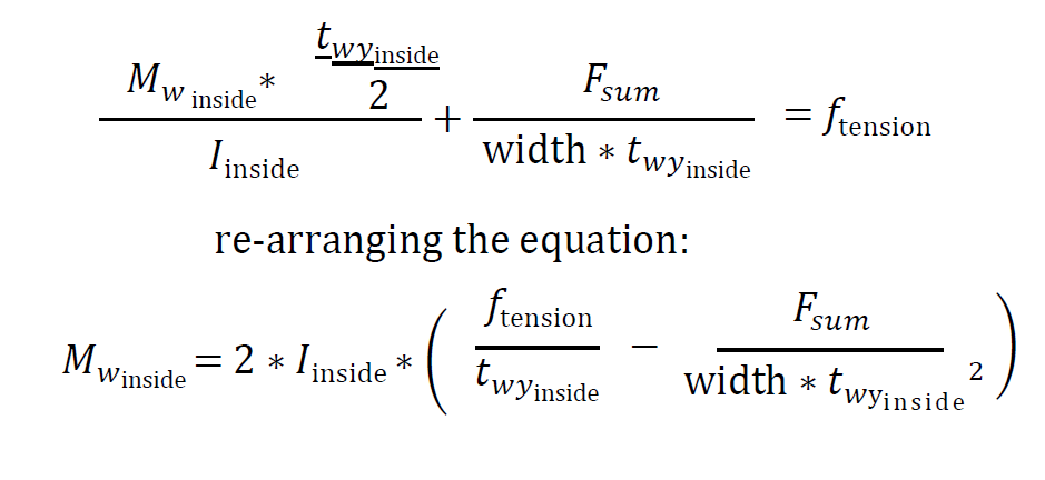
To calculate the cracking moment for a mild reinforced wythe (assuming the tension wythe will crack before or at the same time as the compression wythe) the following equation is used:
The stress equation is similar for prestress with the precompressive force added to the tension wythe and thus increasing the M cr.
Step 4. Calculate the equivalent distributed wind load.
Now, the applied wind load that causes the cracking moment can be back calculated. Calculate the equivalent load that the inside wythe using the cracking moment equation in step 3 and the equations to the right.
To determine if the assumed slip is correct the slip needs to be recalculated for verification. The two components of slip Axial and Rotation for the end location are iterated by the program. Step 5a explains the Bending Slip and 5b Axial Slip.
Step 5a. Bending Slip Calculation.
Rotation at the end connector location θ can be calculated using published equations. For this program a distributed load is used.
Step 5b. Axial Slip Calculation.
To calculate axial slip, one must account for each of the connector forces along beam based on the assumed slip distribution.
Then the axial forces from the connectors combined with the row spacing are used with the well known elastic axial deformation equation (PL/AE) for both wythes.
Step 6. Calculate total end slip from steps 5a and 5b.
Almost there... The axial slip and the rotational slip act in different directions thus the need for the minus sign.
The total slip in step 6 is now compared to the slip calculated in step 1. The program does this quickly and does the iteration until the numbers converge at 10 decimal places. This usually takes between 50 - 70 iterations.
Step 7. Calculate the cracking moment.
Where Mcr = is the moment required to crack the section calculated as in-lbs (output is kip-ft)


